As variable speed drive technology improved and sequencing the opening of the contactor to coordinate with the termination of current flow to the motor became reliable, the need for a contactor to break an arc took second place to the use of a contactor for isolation purposes.
This meant that the more robust and more expensive Nema contactor was not required.
Motor contactors, whether used as output contactors of inverters or DC thyristor drives, are mechanically designed so that the main contacts close before the auxiliary contacts and the auxiliary contacts open before the main contacts. This delay will be only milliseconds, which is enough to coordinate with the drive to stop current flow when a contactor is de-energized. The auxiliary contacts shut the drive off prior to the opening of the main contacts. Likewise, when the drive is turned on and motor contactor is closed, the auxiliary contact will prevent the drive from trying to produce current flow before the main contacts are closed.
An ohm meter can be connected to the auxiliary contact and then the main contact can be manually closed and opened while observing the meter to see that the coordination between the main contact and the auxiliary is present.
The sequencing of the contactor is initiated by the drive. A run signal to the drive will cause the drive to close the motor contactor, once the auxiliary is closed, current can flow. When the drive receives a stop command, the drive will begin to sequence off, the motor contactor is de-energized by the drive and the drive sees the auxiliary contact opening. By the time the main contact opens, current flow has stopped.
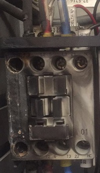
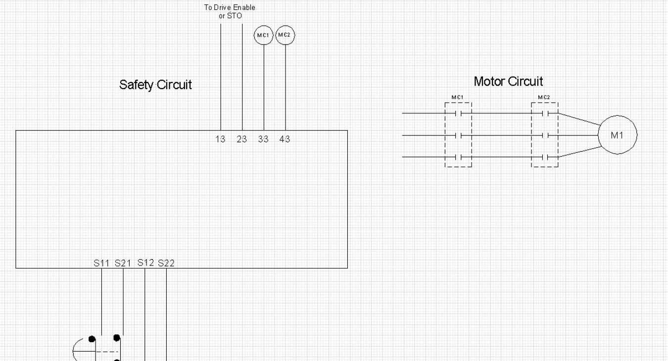
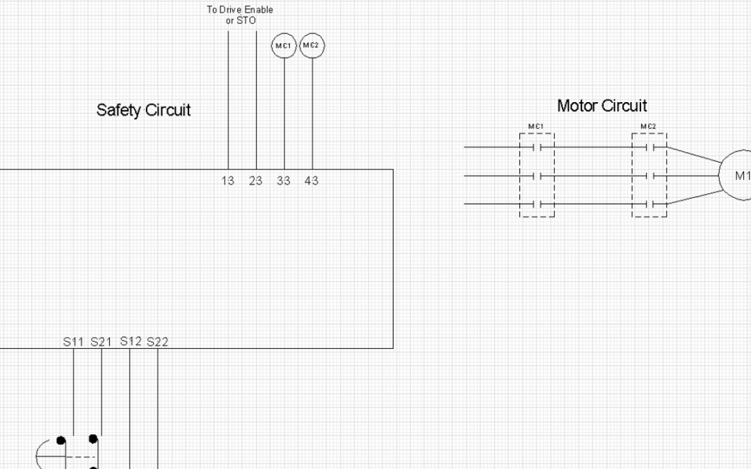
Today, we see improper implementation of safety relays. The purpose of a safety relay is to assure a safe working environment for individuals performing work on a section of a machine which has not been electrically locked out or to stop motion of the machine if a person has entered an unsafe location. Often, we see a safety relay connected in a way that removes power from the motor contactor without any coordination with the drive. The opening of the auxiliary contact on the motor contactor without the drive also being sequenced off, may or may not result in a condition were the main contacts open after the current stops flowing. The result is reduced life of the motor contactor and in some cases voltage transients are produced that destroy the semiconductors in the drive’s power circuit and can possibly cause a surge suppressor to blow up.


